If you have a site that is impacted by subsurface contamination and is targeted for thermal remediation, it will require in-depth research, planning, and calculations to create a successful design for thermal remedy. This design includes predictions of remediation progress (e.g., schedule, power usage, subsurface heat-up) which is calculated using numerical modeling.
Before going down the thermal route, you will need to accurately characterize the site parameters such as geology, hydrogeology, target treatment zone (TTZ), and site contaminates. Sites without a detailed and high-quality site characterization will lead to inaccurate project estimations such as cost, duration, equipment types and sizing.
All thermal remediation sites are different and complex in their own way and need a flexible modeling and predictive tool that can be customized for the actual site conditions. This tool provides accurate design data and performance predictions to ensure a successful in situ thermal remediation (ISTR) project.
What does the numerical model do and how does it work?
Numerical modeling is used to determine out how a site will respond to the input of thermal energy from heaters or steam, and extraction expectations of steam, liquid, and vapor flow into the above grade process treatment system. The model will output operational duration, energy usage, average temperature progression, porosity changes, and other helpful data. In addition, these modeled outputs can help determine the best treatment equipment for the site and an estimation of project costs.
An efficient and successful numerical modeling approach is to use a multi-layered, transient box model to track the changes in energy of the system by calculating the water and energy balances at certain time steps.
Figure 2 shows a box model of how the heat energy inputs and outputs (red), steam energy inputs and outputs (purple), and water inputs and outputs (blue) are calculated.
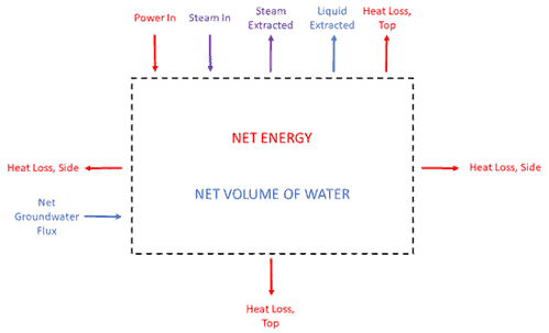
Figure 2. Example of energy and water balances in a simple box model
The transient box model can incorporate multiple layers that correspond to the geology seen at the site, with each layer having its own geologic and hydrogeologic parameters.
The site’s parameters need to be accurately represented in the numerical model to be able to calculate energy input, energy transfer, and heat-up within the target treatment zone (TTZ). To run the numerical model of the site requires assimilating all the data received from the client and determining the optimal layer distribution that accounts for changes in lithology, hydrological boundaries, and the geometry of the TTZ. Each layer is treated as its own element or box (figure 2) through which energy and water are transferred, allowing individual portions of the treatment volume to be examined more carefully.
The importance of accurate and detailed site parameters
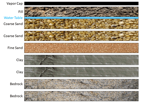
The site’s parameters need to be accurately represented in the numerical model to be able to accurately calculate energy input, energy transfer, and heat-up within the subsurface of the site. We base our model on detailed site information provided by the client such as geology, hydrogeology, key soil parameters, and a 3D understanding of the treatment volume. To run the numerical model of the site requires assimilating all the data received from the client and determining the optimal layer distribution that accounts for changes in lithology, hydrological boundaries, and the geometry of the target treatment zone (TTZ). Each layer is treated as its own element or box through which energy and water are transferred, allowing individual portions of the treatment volume to be examined more carefully. Figure 3 shows an example of distributed layers in a site’s numerical model.
Once all the custom parameters for a site are entered into the model, the model outputs data for each layer. This information includes an energy and water balance, subsurface temperature curves, operation duration, vapor and liquid extraction rates, and estimated project utility usage (e.g., electricity for TCH or ERH or natural gas for steam). Figure 4 shows predicted subsurface temperatures over time for a nine layer model.
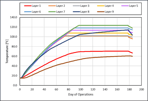
Figure 5 below shows an example of how the model predicted heat-up (black dashed line) can be used to track actual site heat-up progress (red line). This type of evaluation can be used to adjust energy input and vapor and liquid extraction strategies to ensure that the project is completed on schedule.
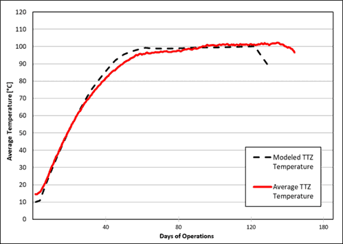
The figure also shows that through a simplified representation of the treatment volumes and when the subsurface is properly understood, modeling can be an accurate and reliable tool for predicting progress towards target temperature.
In summary, the primary use of a model is to understand the total volume of soil, water, and air in the model domain and how much groundwater is flowing through to estimate the site heat capacity and therefore the energy required to heat the volume to the target temperature.
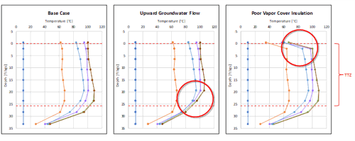
A model is also useful in the design phase for evaluating potential challenges, such as groundwater flow at certain depths, the importance of the R-value of a vapor cover, and sensitivity to starting groundwater levels and saturation. By simulating high and low values of key factors, sensitivity studies are developed that indicate where to focus and optimize the design.
Figure 6 is an example where the upward flow of groundwater and a poor vapor cover led to less-than-optimal heating of the site.
Overall, the numerical modeling of thermal remediation provides a solid baseline for clients and engineers to know what to expect during a project. It is useful for verifying and informing the design, tracking the progress of a project during operations, and reflecting on how a project performed relative to expectations throughout its operation.
Check out this webinar recording about thermal modeling if you are interested in learning more: https://terratherm.com/webinar/in-situ-thermal-remediation-modeling-the-basis-of-design/
01.13.22

Sophia LaRoche
Sophia LaRoche is one of our Data Managers. As a Data Manager, she monitors and processes real-time data that comes in from the field and shares with the project team. She is also involved in system design support, work plan preparation, and engineering fi...